首页 文章 精选 留言 我的

精选列表

搜索[部署],共10000篇文章
优秀的个人博客,低调大师

Lync Server 2010的部署系列_第三章 证书、架构、DNS规划

一、证书规划 组件 使用者名称 使用者备用名称条目/顺序 证书颁发机构 (CA) 备注 边缘外部接口 Sip.Gianthard.com (对外的sip连接地址) sip.domainother.com (如果有其他域名,可选) 公共(最佳) 分配给以下边缘服务器角色 外部接口: SIP 访问边缘 Web 会议边缘 A/V 边缘 边缘内部接口 Edge.Gianthard.com (边缘服务器的FQDN) 无 专用 分配给以下边缘服务器角色: 内部接口: 边缘 反向代理 (可以与边缘外部接口合并为一个证书) Rp.Gianthard.com (web外部服务) dialin.Gianthard.com meet.Gianthard.com 公共(最佳) 通讯簿服务、通讯组扩展和 Lync IP 设备发布规则。使用者备用名称包括: 外部 Web 服务FQDN 电话拨入式会议 联机会议发布规则 下一个跃点池 pool.Gianthard.com (前端池的FQDN) sip.domainother.com (可选) pool.Gianthard.com Front.Gianthard.com admin.Gianthard.com dialin.Gianthard.com meet.Gianthard.com 专用 分配给下一个跃点池中的以下服务器和角色: Pool中的前端 二、架构规划 具体端口请参考《防火墙网络端口开放检查》。 除OCS 2007 R2使用windows server 2003 r2 64位操作系统,其余都为windows server 2008 r2。 注:边缘服务器访问接口的FQDN(Sip.Gianthard.com)和边缘服务器内部接口FQDN(Edge.Gianthard.com)建议是设为不相同的。虽然没有KB明确指出可以设为一样。从理论上是可以设为一样的。但是考虑到避免内部和外部的DNS服务器的A记录分别正确解析到内部和外部接口的IP地址,以及排错时区分外部和内部接口的FQDN。最好为不一样。 网络名称规划: 服务器功能 FQDN IP地址 其他 AD(Lync Server文件) DC.Gianthard.com 192.168.1.11 充当lync文件共享和证书。 OCS 2007 R2标准版 OCS2007R2.Gianthard.com 192.168.1.12 池 Pool.Gianthard.com 192.168.1.21 无 Lync Server前端 Front.Gianthard.com 192.168.1.21 可与A/V会议、中介服务器并置 Lync Server后端数据库 实验环境,安装在DC当中 192.168.1.11 可并置存档服务器和监控服务器的数据库实例。 Lync Server监控 lyncother.Gianthard.com 192.168.1.22 可与存档服务器并置 Lync Server归档 可与监控服务器并置 Lync Server群聊 Chat.Gianthard.com 192.168.1.25 无并置方案 Lync Server群聊数据库 ChatSQL.Gianthard.com 192.168.1.26 无并置方案,OS与SQL必须都是英文版本。 Lync Server边缘 (不能加入域) Edge.Gianthard.com 内网 192.168.1.23 内网网卡IP地址 Sip.Gianthard.com 外网 172.20.0.2 DMZ网卡IP地址 Exchange 2010标准 Exchange.Gianthard.com 192.168.1.13 HTTP反向代理 TMG.Gianthard.com 192.168.1.15 内网网卡IP地址 172.20.0.1 DMZ网卡IP地址 10.0.10.10 外网网卡IP地址 MOSS 2010 MOSS.Gianthard.com 192.168.1.14 VOIP网关 无法加入域 192.168.1.24 硬件PSTN网关 三、DNS规划: 简单 URL规划: 简单 URL 示例 会议 https://meet.Gianthard.com 拨入 https://dialin.Gianthard.com 管理 https://admin.Gianthard.com 边缘拓扑所需的DNS记录(全为手工创建记录): 位置 类型 FQDN IP地址/FQDN 端口 映射位置/注释 外部 DNS A sip.Gianthard.com 外网IP地址 不适用 SIP 访问边缘外部接口 Web 会议边缘外部接口 A/V 边缘外部接口(Gianthard) 外部 DNS A sip.domainother.com (如果有其他域名,可选) 外网IP地址 SIP 访问边缘外部接口 (其他域名) 外部 DNS SRV _sip._tls.Gianthard.com sip.Gianthard.com 443 SIP 访问边缘外部接口 (sip.Gianthard.com) 用于实现在外部自动配置 Lync 2010 客户端 外部 DNS SRV _sip._tls.domainother.com (如果有其他域名,可选) sip.domainother.com 443 SIP 访问边缘外部接口 (sip.domainother.com) 用于实现在外部自动配置 Lync 2010 客户端。 外部 DNS SRV _sipfederationtls._tcp.Gianthard.com sip.Gianthard.com 5061 SIP 访问边缘外部接口 (sip.Gianthard.com) 用于实现称为“允许的 SIP 域”的联盟伙伴(在以前版本中称为增强联盟)的自动 DNS 发现。 外部 DNS SRV _sipfederationtls._tcp.domainother.com (如果有其他域名,可选) sip.domainother.com 5061 SIP 访问边缘外部接口 (sip.domainother.com) 用于实现称为“允许的 SIP 域”的联盟伙伴(在以前版本中称为增强联盟)的自动 DNS 发现。 内部 DNS A Edge.Gianthard.com 192.168.1.23 不适用 合并边缘内部接口 反向代理所需的DNS记录(全为手工创建记录): 位置 类型 FQDN IP地址 端口 映射位置/注释 外部 DNS A sip.Gianthard.com 外部IP地址 不适用 用于发布通讯簿服务、通讯组扩展和会议内容。 外部 DNS A dialin.Gianthard.com 外部IP地址 在外部发布的电话拨入式会议 外部 DNS A meet.Gianthard.com 外部IP地址 在外部发布的会议 外部 DNS A RP.Gianthard.com 外部IP地址 Lync Server 2010 外部 Web 服务 FQDN 外部 DNS A TMG.Gianthard.com 外部IP地址 TMG服务器的FQDN。 内部所需的 DNS 记录(一部份为手工创建记录): 位置 类型 FQDN IP地址 端口 映射位置/注释 内部 DNS A pool.Gianthard.com 192.168.1.21 不适用 池(手工创建) 内部 DNS A fe01.domainother.com (如果有,可选) 192.168.1.21 池的多域名(手工创建) 内部 DNS A sql01.Gianthard.com (由于实验环境的原因,这里显示为DC.Gianthard.com) 192.168.1.11 运行 Microsoft SQL Server 2008 或 Microsoft SQL Server 2005 的 Pool01 后端服务器(加入域后自动生成) 内部 DNS A Front.Gianthard.com 192.168.1.21 前端服务器(加入域后自动生成) 内部 DNS A sip.domainother.com (如果有,可选) 192.168.1.21 Lync 2010 客户端的自动配置在内部工作时需要(手工创建) 内部 DNS A dialin.Gianthard.com 192.168.1.21 在内部发布的电话拨入式会议(手工创建) 内部 DNS A meet.Gianthard.com 192.168.1.21 在内部发布的会议(手工创建) 内部 DNS A admin.Gianthard.com 192.168.1.21 在内部发布的 Microsoft Lync Server 2010 Control Panel(手工创建) 内部 DNS SRV _sipinternaltls._tcp.Gianthard.com pool.Gianthard.com 5061 Lync 2010 客户端的自动配置在内部工作时需要(手工创建) 内部 DNS SRV _sipinternaltls._tcp.domainother.com (如果有其他域名,可选) pool.domainother.com 5061 Lync 2010 客户端的自动配置在内部工作时需要(手工创建) 本文转自 zhou_ping 51CTO博客,原文链接:http://blog.51cto.com/yuntcloud/1560529,如需转载请自行联系原作者

优秀的个人博客,低调大师

再聊负载均衡SLB的主备可用区和高可用部署最佳实践

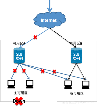
1.概述 阿里云负载均衡SLB的主备可用区提供了多个层级的高可用,可阅读《负载均衡SLB高可用的四个层次》。但很多用户常常在下单选购时,对可用区的选择感到困惑。到底如何选择SLB的主备可用区,如何搭配不同可用区的ECS,来构建高可靠应用系统呢?客官请听下文分解。 首先,我们要搞清楚一个事实,负载均衡SLB的可用区设计的初衷,是用来抵御可用区(机房)级别的重大灾情的,比如机房整体掉电,机房出口光缆中断等,即当某个可用区整体不可用时,备可用区才派上用场,也就是说只在上述情况下,SLB的主备可用区才会发生倒换。而并非用户的某个实例出现故障,就会自动发生主备倒换的,这是一个很典型的误区。 图注:当可用区A整体不可用时,SLB才会发生主备倒换 那么主备可用区应该如何选择比较合适呢?对于SLB的主可用而言,主要看用户的ECS主要分布在那个可用区,SL

优秀的个人博客,低调大师

【高级】思科设备部署电信运营商城域网架构及配置实战

实验拓扑: GNS3 0.8.6 +c3725-adventerprisek9-mz.124-15.T5 实验要求: 1.通过ISIS协议将AS内部的直连和环回口路由宣告。 2.通过配置IBGP协议建立邻居将所有的用户业务路由(大客户和PPPOE拨号)宣告。 3.通过配置路由反射器实现市内、省内业务路由互传。 4.通过建立EBGP邻居实现全省和国干互联网路由互传。 5.通过配置黑洞路由实现用户业务网段聚合。 实验步骤及验证: 1.接口及ip地址规划: 路由器 接口 ip地址 R1 F0/0 12.0.0.1/30 R1 F0/1 16.0.0.1/30 R1 Loopback 0 1.1.1.1/32 R1 Loopback 10 192.168.1.1/30 R1 Loopback 20 192.168.2.1/32 R1 Loopback 30 192.168.2.3/32 R2 F0/0 12.0.0.2/30 R2 F2/0 23.0.0.1/30 R2 F0/1 25.0.0.1/30 R2 F1/0 26.0.0.1/30 R2 loopback 0 2.2.2.2/32 R3 F0/0 23.0.0.2/30 R3 F1/0 34.0.0.1/30 R3 F0/1 37.0.0.1/30 R3 loopback 0 3.3.3.3/32 R4 F0/0 34.0.0.2/30 R4 F0/1 48.0.0.1/30 R4 loopback 0 4.4.4.4/32 R4 loopback 10 192.168.4.1/30 R5 F0/0 25.0.0.2/30 R5 F0/1 56.0.0.1/30 R5 Loopback 0 5.5.5.5/32 R5 Loopback 10 192.168.3.1/30 R6 F0/1 56.0.0.2/30 R6 F0/0 16.0.0.2/30 R6 F1/0 26.0.0.2/30 R6 F2/0 67.0.0.1/30 R6 loopback 0 6.6.6.6/32 R7 F0/0 67.0.0.2/30 R7 F0/1 37.0.0.2/30 R7 F1/0 78.0.0.1/30 R7 loopback 0 7.7.7.7/32 R8 F0/0 78.0.0.2/30 R8 F0/1 48.0.0.2/30 R8 loopback 0 8.8.8.8/32 R8 loopback 10 192.168.5.1/30 2.配置脚本: R1 R1(config)#int f0/0 R1(config-if)#ip add12.0.0.1 255.255.255.252 R1(config-if)#no sh R1(config)#int f0/1 R1(config-if)#ip add16.0.0.1 255.255.255.252 R1(config-if)#no sh R1(config-if)#int lo 0 R1(config-if)#ip add1.1.1.1 255.255.255.255 R1(config-if)#int lo 10//模拟下挂的30位掩码静态大客户业务网段// R1(config-if)#ip add192.168.1.1 255.255.255.252 R1(config-if)#int lo 20//模拟下挂的32位掩码PPPOE用户// R1(config-if)#ip add192.168.2.1 255.255.255.255 R1(config-if)#int lo 30//模拟下挂的32位掩码PPPOE用户// R1(config-if)#ip add192.168.2.3 255.255.255.255 R2 R2(config)#int f0/0 R2(config-if)#ip add 12.0.0.2 255.255.255.252 R2(config-if)#no sh R2(config-if)#int f0/1 R2(config-if)#ip add 25.0.0.1 255.255.255.252 R2(config-if)#no sh R2(config-if)#int f1/0 R2(config-if)#ip add 26.0.0.1 255.255.255.252 R2(config-if)#no sh R2(config-if)#int f2/0 R2(config-if)#ip add 23.0.0.1 255.255.255.252 R2(config-if)#no sh R2(config-if)#int lo 0 R2(config-if)#ip add 2.2.2.2 255.255.255.255 R3 R3(config)#int f0/0 R3(config-if)#ip add 23.0.0.2255.255.255.252 R3(config-if)#no sh R3(config-if)#int f0/1 R3(config-if)#ip add 37.0.0.1255.255.255.252 R3(config-if)#no sh R3(config-if)#int f1/0 R3(config-if)#ip add 34.0.0.1255.255.255.252 R3(config-if)#no sh R3(config-if)#int lo 0 R3(config-if)#ip add 3.3.3.3255.255.255.255 R4 R4(config)#int f0/0 R4(config-if)#ip add 34.0.0.2255.255.255.252 R4(config-if)#no sh R4(config-if)#int f0/1 R4(config-if)#ip add 48.0.0.1255.255.255.252 R4(config-if)#no sh R4(config-if)#int lo 0 R4(config-if)#ip add 4.4.4.4255.255.255.255 R4(config-if)#intlo 10//模拟下挂的30位掩码静态大客户业务网段// R4(config-if)#ip add 192.168.4.1255.255.255.252 R5 R5(config)#int f0/0 R5(config-if)#ip add 25.0.0.2255.255.255.252 R5(config-if)#no sh R5(config-if)#int f0/1 R5(config-if)#ip add 56.0.0.1255.255.255.252 R5(config-if)#no sh R5(config-if)#intlo 10//模拟下挂的30位掩码静态大客户业务网段// R5(config-if)#ip add 192.168.3.1255.255.255.252 R5(config-if)#int lo 0 R5(config-if)#ip add 5.5.5.5255.255.255.255 R6 R6(config)#int f0/1 R6(config-if)#ip add 56.0.0.2255.255.255.252 R6(config-if)#no sh R6(config-if)#int f0/0 R6(config-if)#ip add 16.0.0.2255.255.255.252 R6(config-if)#no sh R6(config-if)#int f1/0 R6(config-if)#ip add 26.0.0.2255.255.255.252 R6(config-if)#no sh R6(config-if)#int f2/0 R6(config-if)#ip add 67.0.0.1255.255.255.252 R6(config-if)#no sh R6(config-if)#int lo 0 R6(config-if)#ip add 6.6.6.6255.255.255.255 R7 R7(config)#int f0/0 R7(config-if)#ip add 67.0.0.2255.255.255.252 R7(config-if)#no sh R7(config-if)#int f0/1 R7(config-if)#ip add 37.0.0.2255.255.255.252 R7(config-if)#no sh R7(config-if)#int f1/0 R7(config-if)#ip add 78.0.0.1255.255.255.252 R7(config-if)#no sh R7(config)#int lo 0 R7(config-if)#ip add 7.7.7.7255.255.255.255 R8 R8(config)#int f0/0 R8(config-if)#ip add 78.0.0.2255.255.255.252 R8(config-if)#no sh R8(config-if)#int f0/1 R8(config-if)#ip add 48.0.0.2255.255.255.252 R8(config-if)#no sh R8(config-if)#intlo 10//模拟下挂的30位掩码静态大客户业务网段// R8(config-if)#ip add 192.168.5.1255.255.255.252 R8(config-if)#int lo 0 R8(config-if)#ip add 8.8.8.8255.255.255.255 ---------------------------以上是ip地址配置---------------------------------- R1 R1(config)#router isis//开启ISIS协议// R1(config-router)#net 49.0001.0010.0100.1001.00//通过环回口翻译得出net地址// R1(config-router)#is-type level-1//指定R1为L1型路由器// R1(config)#int range f0/0 - 1 ,lo 0 R1(config-if-range)#ip router isis//在R1的互连接口和环回口下通告ISIS协议// R2//R2上ISIS配置同R1这里就不再赘述了// R2(config)#router isis R2(config-router)#net 49.0001.0020.0200.2002.00 R2(config-router)#is-type level-1-2//指定R2为L1-2路由器// R2(config)#int range f0/0 - 1 ,f1/0 ,f2/0 ,lo 0 R2(config-if-range)#ip router isis R3//R3上ISIS配置同R1这里就不再赘述了// R3(config)#router isis R3(config-router)#net 49.0002.0030.0300.3003.00 R3(config-router)#is-type level-2//指定R3为L2路由器// R3(config)#int range f0/0 - 1 ,lo 0 R3(config-if-range)#ip router isis R5//R5上ISIS配置同R1这里就不再赘述了// R5(config)#router isis R5(config-router)#net 49.0001.0050.0500.5005.00 R5(config-router)#is-type level-1//指定R5为L1路由器// R5(config)#int range f0/0 - 1 ,lo 0 R5(config-if-range)#ip router isis R6//R6上ISIS配置同R1这里就不再赘述了// R6(config)#router isis R6(config-router)#net 49.0001.0060.0600.6006.00 R6(config-router)#is-type level-1-2//指定R6为L1-2路由器// R6(config)#int range f0/0 - 1 ,f1/0 ,f2/0 ,lo 0 R6(config-if-range)#ip router isis R7//R7上ISIS配置同R1这里就不再赘述了// R7(config)#router isis R7(config-router)#net 49.0002.0070.0700.7007.00 R7(config-router)#is-type level-2//指定R7为L2路由器// R7(config)#int range f0/0 - 1 ,lo 0 R7(config-if-range)#ip router isis ---------------------------以上是IS-IS路由配置---------------------------------- 实验验证: 在R7上查看路由表发现可以学到通告了ISIS的路由器的环回口地址,Ping 1.1.1.1可以通信,证明ISIS协议内部互连接口及环回口间可以通信。 ------------------------以上是IS-IS AS内部互通验证--------------------------- R4 R4(config)#router ospf 110//开启OSPF协议进程号为110// R4(config-router)#router-id 4.4.4.4//使用环回口地址作为RID// R4(config-router)#network 4.4.4.4 0.0.0.0 area 1 R4(config-router)#network 48.0.0.0 0.0.0.3 area 1//通告互连接口及环回口// R8//R8上OSPF配置同R4这里就不再赘述了// R8(config)#router ospf 110 R8(config-router)#router-id 8.8.8.8 R8(config-router)#network 48.0.0.0 0.0.0.3 area 1 R8(config-router)#network 8.8.8.8 0.0.0.0 area 1 在R8上ping R4的环回口(4.4.4.4)可以通信,证明OSPF内部互连接口及环回口间可以通信。 ------------------------以上是OSPF AS内部互通验证--------------------------- 注意: 在配置中,两个AS间关口局设备的互连接口不需要通告到IGP中。 R1 R1(config)#router bgp 65001//在R1上开启BGP协议// R1(config-router)#bgp router-id 1.1.1.1//指定BGP的RID// R1(config-router)#neighbor 2.2.2.2 remote-as 65001//R1作为BRAS/SR设备需要和所有市干/省干设备(本例中为R2,6,3,7)建立IBGP邻居关系以传递下挂业务网段路由,所以remote-as为同一AS号// R1(config-router)#neighbor 2.2.2.2 update-source lo 0//使用自身的环回口(环回口更加稳定)和对放建立IBGP邻居关系// R1(config-router)#neighbor 6.6.6.6 remote-as 65001 R1(config-router)#neighbor 6.6.6.6 update-source lo 0 R1(config-router)#neighbor 3.3.3.3 remote-as 65001 R1(config-router)#neighbor 3.3.3.3 update-source lo 0 R1(config-router)#neighbor 7.7.7.7 remote-as 65001 R1(config-router)#neighbor 7.7.7.7 update-source lo 0 注意: BGP的邻居关系需手工双向建立(即两相情愿型),在建立邻居的对端设备上也要手工指定邻居。 R2//R2作为市干设备需要和所有BARS/SR设备建立邻居关系以获得业务网段路由,同时还需和直连路由器建立邻居关系以提供路由的冗余,R2建立IBGP邻居关系配置同R1这里就不再赘述了// R2(config)#router bgp 65001 R2(config-router)#bgp router-id 2.2.2.2 R2(config-router)#neighbor 1.1.1.1 remote-as 65001 R2(config-router)#neighbor 1.1.1.1 update-source lo 0 R2(config-router)#neighbor 5.5.5.5 remote-as 65001 R2(config-router)#neighbor 5.5.5.5 update-source lo 0 R2(config-router)#neighbor 6.6.6.6 remote-as 65001 R2(config-router)#neighbor 6.6.6.6 update-source lo 0 R2(config-router)#neighbor 3.3.3.3 remote-as 65001 R2(config-router)#neighbor 3.3.3.3 update-source lo 0 R3//R3作为省干设备需要和所有BARS/SR设备建立邻居关系以获得业务网段路由,同时还需和直连路由器建立邻居关系以提供路由的冗余,R3建立IBGP邻居关系配置同R1这里就不再赘述了// R3(config)#router bgp 65001 R3(config-router)#bgp router-id 3.3.3.3 R3(config-router)#neighbor 1.1.1.1 remote-as 65001 R3(config-router)#neighbor 1.1.1.1 update-source lo 0 R3(config-router)#neighbor 5.5.5.5 remote-as 65001 R3(config-router)#neighbor 5.5.5.5 update-source lo 0 R3(config-router)#neighbor 2.2.2.2 remote-as 65001 R3(config-router)#neighbor 2.2.2.2 update-source lo 0 R3(config-router)#neighbor 7.7.7.7 remote-as 65001 R3(config-router)#neighbor 7.7.7.7 update-source lo 0 R5//R5作为BRAS/SR设备需要和所有市干/省干设备(本例中为R2,6,3,7)建立IBGP邻居关系以传递下挂业务网段路由,R5配置同R1,在此就不再赘述了// R5(config)#router bgp 65001 R5(config-router)#bgp router-id 5.5.5.5 R5(config-router)#neighbor 2.2.2.2 remote-as 65001 R5(config-router)#neighbor 2.2.2.2 update-source lo 0 R5(config-router)#neighbor 6.6.6.6 remote-as 65001 R5(config-router)#neighbor 6.6.6.6 update-source lo 0 R5(config-router)#neighbor 3.3.3.3 remote-as 65001 R5(config-router)#neighbor 3.3.3.3 update-source lo 0 R5(config-router)#neighbor 7.7.7.7 remote-as 65001 R5(config-router)#neighbor 7.7.7.7 update-source lo 0 R6//R6作为市干设备需要和所有BARS/SR设备建立邻居关系以获得业务网段路由,同时还需和直连路由器建立邻居关系以提供路由的冗余,R6建立IBGP邻居关系配置同R1这里就不再赘述了// R6(config)#router bgp 65001 R6(config-router)#bgp router-id 6.6.6.6 R6(config-router)#neighbor 1.1.1.1 remote-as 65001 R6(config-router)#neighbor 1.1.1.1 update-source lo 0 R6(config-router)#neighbor 5.5.5.5 remote-as 65001 R6(config-router)#neighbor 5.5.5.5 update-source lo 0 R6(config-router)#neighbor 2.2.2.2 remote-as 65001 R6(config-router)#neighbor 2.2.2.2 update-source lo 0 R6(config-router)#neighbor 7.7.7.7 remote-as 65001 R6(config-router)#neighbor 7.7.7.7 update-source lo 0 R7//R7作为省干设备需要和所有BARS/SR设备建立邻居关系以获得业务网段路由,同时还需和直连路由器建立邻居关系以提供路由的冗余,R7建立IBGP邻居关系配置同R1这里就不再赘述了// R7(config)#router bgp 65001 R7(config-router)#bgp router-id 7.7.7.7 R7(config-router)#neighbor 1.1.1.1 remote-as 65001 R7(config-router)#neighbor 1.1.1.1 update-source lo 0 R7(config-router)#neighbor 5.5.5.5 remote-as 65001 R7(config-router)#neighbor 5.5.5.5 update-source lo 0 R7(config-router)#neighbor 6.6.6.6 remote-as 65001 R7(config-router)#neighbor 6.6.6.6 update-source lo 0 R7(config-router)#neighbor 3.3.3.3 remote-as 65001 R7(config-router)#neighbor 3.3.3.3 update-source lo 0 R1 R1(config)#ip route 192.168.2.0 255.255.255.0 null 0//指定一条到PPPOE用户汇总网段的静态路由下一跳为null 0(黑洞路由,数据到这就会被丢弃)// R1(config)#router bgp 65001//在BGP下宣告路由// R1(config-router)#network 192.168.1.0 mask 255.255.255.252 R1(config-router)#network 192.168.2.0 mask 255.255.255.0 注意: 通过建立BGP邻居关系传递路由时,前提条件是路由器的路由表中一定要有该条路由条目,并且必须是匹配的(即网络号和掩码必须相同)。 R5 R5(config)#router bgp 65001//在R5上把下挂的30位掩码大客户路由通过BGP宣告// R5(config-router)#network 192.168.3.0 mask 255.255.255.252 注意: 因为IBGP的水平分割原则,从一个IBGP邻居收到的路由不会发给另一个IBGP邻居,所以需要在市干设备(R2,R6上)指定所有BARS/SR设备为自己的路由反射器客户端,使得每一台BARS/SR设备上都所有业务网段的路由。 R2//在R2上指定所有BARS/SR设备为自己的路由反射器客户端// R2(config-router)#neighbor 1.1.1.1 route-reflector-client R2(config-router)#neighbor 5.5.5.5 route-reflector-client R2(config-router)# bgp cluster-id 123//配置同一层设备相同的组ID使得客户端设备认为路由信息是同一设备传给它的// R6//在R6上指定所有BARS/SR设备为自己的路由反射器客户端// R6(config-router)#neighbor 1.1.1.1 route-reflector-client R6(config-router)#neighbor 5.5.5.5 route-reflector-client //配置同一层设备相同的组ID使得客户端设备认为路由信息是同一设备传给它的// 在R1上查看路由表可以看到通过BGP学习到了同为BARS/SR设备的R5下的业务路由,在R1上ping 192.168.3.1(R5的lo 10模拟下挂业务网段)可以通信,至此全省省内的路由可达,实现省内互通。 ---------------------------以上通过IBGP实现省内互通-------------------------- R4//在国干设备R4上与同一BGP AS中的国干设备R8建立IBGP邻居关系产地业务路由,具体原理及配置上文有详细介绍,这里不再赘述// R4(config)#router bgp 65002 R4(config-router)#bgp router-id 4.4.4.4 R4(config-router)#neighbor 8.8.8.8 remote-as 65002 R4(config-router)#neighbor 8.8.8.8 update-source lo 0 R8//在国干设备R8上与同一BGP AS中的国干设备R4建立IBGP邻居关系产地业务路由,具体原理及配置上文有详细介绍,这里不再赘述// R8(config)#router bgp 65002 R8(config-router)#bgp router-id 8.8.8.8 R8(config-router)#neighbor 4.4.4.4 remote-as 65002 R8(config-router)#neighbor 4.4.4.4 update-source lo 0 注意: 需要在两个BGP AS间配置EBGP邻居来传递两省间跨越互联网(国干)的通信,EBGP邻居建立的条件是邻居间可以通信,所以需要在两个AS的关口局设备上互指静态路由。 R3 R3(config)#ip route 4.4.4.4 255.255.255.255 34.0.0.2 R4 R4(config)#ip route 3.3.3.3 255.255.255.255 34.0.0.1 //在关口局设备R3,R4上互指静态路由// R7 R7(config)#ip route 8.8.8.8 255.255.255.255 78.0.0.2 R8 R8(config)#ip route 7.7.7.7 255.255.255.255 78.0.0.1 //在关口局设备R7,R8上互指静态路由// R3 R3(config)#router bgp 65001 R3(config-router)#neighbor 4.4.4.4 remote-as 65002//和另一个BGP AS建立EBGP邻居// R3(config-router)#neighbor 4.4.4.4 update-source lo 0 R3(config-router)#neighbor 4.4.4.4 ebgp-multihop 2//EBGP默认有跳数为1的限制所以需要手动将跳数设置为2// R4 R4(config)#router bgp 65002 R4(config-router)#neighbor 3.3.3.3 remote-as 65001//和另一个BGP AS建立EBGP邻居// R4(config-router)#neighbor 3.3.3.3 update-source lo 0 R4(config-router)#neighbor 3.3.3.3 ebgp-multihop 2//EBGP默认有跳数为1的限制所以需要手动将跳数设置为2// R7//这里R7配置同R3,就不再赘述// R7(config)#router bgp 65001 R7(config-router)#neighbor 8.8.8.8 remote-as 65002 R7(config-router)#neighbor 8.8.8.8 update-source lo 0 R7(config-router)#neighbor 8.8.8.8 ebgp-multihop 2 R8//这里R8配置同R4,就不再赘述// R8(config)#router bgp 65002 R8(config-router)#neighbor 7.7.7.7 remote-as 65001 R8(config-router)#neighbor 7.7.7.7 update-source lo 0 R8(config-router)#neighbor 7.7.7.7 ebgp-multihop 2 在R1上查看BGP的路由表发现到达192.168.4.0/30子网的路由已经被优化放入路由表中,但在R1上ping R4的lo 10(192.168.4.1模拟业务网段)不通,继续查看路由表可以找出原因。 这是因为R1上有一条由ISIS的L1-2路由器下发给它的默认路由,所以R1会认为到达192.168.4.0/30子网的下一跳4.4.4.4可达,所以就会优化将此 放入路由表,但是我们继续看路由表可以发现并没有到达4.4.4.4的明细路由,故虽然控制层面的路由有了,但数据层面仍然是不通的。 查看R3路由表发现R3因为配置了静态路由,R3是知道如何到4.4.4.4的,而R3的环回口是通过IGP(ISIS)通告的,所以R1是知道如何到R3的,因此我们可以采用跳板,在R3上告诉所有的IBGP邻居下一跳为自己,在R7上也一样,在市干设备(R2,R6)上同样要告诉所有BARS/SR设备下一跳为自己,同时为了路由冗余,同层设备之间也要相互宣告。 R2 R2(config-router)#neighbor 1.1.1.1 next-hop-self R2(config-router)#neighbor 5.5.5.5 next-hop-self R2(config-router)#neighbor 6.6.6.6 next-hop-self R6 R6(config-router)#neighbor 1.1.1.1 next-hop-self R6(config-router)#neighbor 5.5.5.5 next-hop-self R6(config-router)#neighbor 2.2.2.2 next-hop-self R3 R3(config-router)#neighbor 1.1.1.1 next-hop-self R3(config-router)#neighbor 2.2.2.2 next-hop-self R3(config-router)#neighbor 7.7.7.7 next-hop-self R3(config-router)#neighbor 5.5.5.5 next-hop-self R7 R7(config-router)#neighbor 1.1.1.1 next-hop-self R7(config-router)#neighbor 5.5.5.5 next-hop-self R7(config-router)#neighbor 6.6.6.6 next-hop-self R7(config-router)#neighbor 3.3.3.3 next-hop-self 注意: 假设R3与R4之间链路故障,则R3与R4不可以建立EBGP邻居关系,只有R4通过IBGP邻居关系将业务路由传递给R8,R8通过EBGP邻居关系将路由传给R7,R7会通过IBGP邻居关系传路由给R3,R6,但R3,R6因为IBGP的水平分割原则将不会传路由给R2有可能出现两省间业务网段通信问题,所以需要将所有的市干设备作为省干设备的路由反射器客户端,打破水平分割从而传路由。 R3 R3(config-router)#neighbor 2.2.2.2 route-reflector-client R3(config-router)#bgp cluster-id 321//配置同一层设备相同的组ID使得客户端设备认为路由信息是同一设备传给它的// R7 R7(config-router)#neighbor 6.6.6.6 route-reflector-client R7(config-router)#bgp cluster-id 321//配置同一层设备相同的组ID使得客户端设备认为路由信息是同一设备传给它的// 在R1上使用loopback 10作为源(模拟的30位掩码大客户业务网段)Ping R4的loopback 10(模拟的其他省业务网段),R8的loopback 10(模拟的其他省业务网段)可以通信,同时traceroute可以发现实现了路由的冗余和负载,至此实现跨越互联网的两省通信,实验完成。 实验总结: 1.ISIS协议因为其收敛快速,易于扩展,通常在运营商的架构中用来作为IGP运行设备互联接口和环回口间的通信。2.BGP协议作为目前唯一的EGP主要用来传递业务路由到AS内部以及在AS间传递业务路由。 本文转自Y.weisheng 51CTO博客,原文链接:http://blog.51cto.com/yuan2/1586561,如需转载请自行联系原作者

优秀的个人博客,低调大师

DNS部署(四)之lvs+keepalived+bind架构高可用负载均衡DNS系统

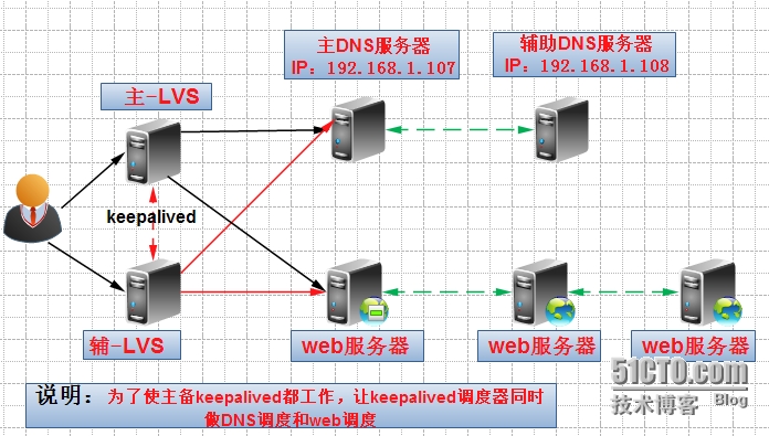
1、网络拓扑 2、环境描述 系统描述 IP地址 作用 LB-master 192.168.1.105 主备负载均衡器(同时做web和DNS调度) LB-backup 192.168.1.106 DNS-master 192.168.1.107 VIP:192.168.1.30(LVS DNS节点互为主辅同步) DNS-backup 192.168.1.108 Web节点组 192.168.1.201-203 VIP:192.168.1.40(LVS web节点) 3、配置LVS调度器keepalived的配置文件 keepalived配置双vrrp instance,分别为:WEB实例和DNS实例。 3.1 主LVS上keepalived的配置文件内容: [root@lvs-M ~]#cat /etc/keepalived/keepalived.conf ! ConfigurationFile for keepalived global_defs { notification_email { acassen@firewall.loc failover@firewall.loc sysadmin@firewall.loc } notification_email_fromAlexandre.Cassen@firewall.loc smtp_server 192.168.200.1 smtp_connect_timeout 30 router_id lvs_105 } vrrp_instance VI_WEB { state MASTER interface eth0 virtual_router_id 51 priority 100 advert_int 1 authentication { auth_type PASS auth_pass 1111 } virtual_ipaddress { 192.168.1.40/24 } } #############LVSWEB################ virtual_server 192.168.1.40 80 { delay_loop 6 lb_algorr lb_kindDR nat_mask 255.255.255.0 #persistence_timeout 50 protocol TCP real_server 192.168.1.201 80 { weight 100 TCP_CHECK { connect_timeout 8 nb_get_retry 3 delay_before_retry 3 connect_port 80 } } real_server 192.168.1.202 80 { weight 100 TCP_CHECK { connect_timeout 8 nb_get_retry 3 delay_before_retry 3 connect_port 80 } } real_server 192.168.1.203 80 { weight 100 TCP_CHECK { connect_timeout 8 nb_get_retry 3 delay_before_retry 3 connect_port 80 } } } #############DNSInstance start############### vrrp_instance VI_DNS { state BACKUP interface eth0 virtual_router_id 52 priority 90 advert_int 1 authentication { auth_type PASS auth_pass 1111 } virtual_ipaddress { 192.168.1.30/24 } } ###########LVSDNS####################### virtual_server 192.168.1.30 53 { delay_loop 6 lb_algo rr lb_kind DR nat_mask 255.255.255.0 #persistence_timeout 50 protocol UDP real_server 192.168.1.107 53 { weight 100 TCP_CHECK { connect_timeout 8 nb_get_retry 3 delay_before_retry 3 connect_port 53 } } real_server 192.168.1.108 53 { weight 100 TCP_CHECK { connect_timeout 8 nb_get_retry 3 delay_before_retry 3 connect_port 53 } } } 3.2 备LVS上keepalived的配置文件内容: [root@lvs-S ~]#cat /etc/keepalived/keepalived.conf ! ConfigurationFile for keepalived global_defs { notification_email { acassen@firewall.loc failover@firewall.loc sysadmin@firewall.loc } notification_email_fromAlexandre.Cassen@firewall.loc smtp_server 192.168.200.1 smtp_connect_timeout 30 router_id lvs_106 } vrrp_instance VI_WEB { state BACKUP interface eth0 virtual_router_id 51 priority 90 advert_int 1 authentication { auth_type PASS auth_pass 1111 } virtual_ipaddress { 192.168.1.40/24 } } #############LVSWEB################ virtual_server 192.168.1.40 80 { delay_loop 6 lb_algorr lb_kindDR nat_mask 255.255.255.0 #persistence_timeout 50 protocol TCP real_server 192.168.1.201 80 { weight 100 TCP_CHECK { connect_timeout 8 nb_get_retry 3 delay_before_retry 3 connect_port 80 } } real_server 192.168.1.202 80 { weight 100 TCP_CHECK { connect_timeout 8 nb_get_retry 3 delay_before_retry 3 connect_port 80 } } real_server 192.168.1.203 80 { weight 100 TCP_CHECK { connect_timeout 8 nb_get_retry 3 delay_before_retry 3 connect_port 80 } } } #############DNS Instancestart############### vrrp_instance VI_DNS { state MASTER interface eth0 virtual_router_id 52 priority 100 advert_int 1 authentication { auth_type PASS auth_pass 1111 } virtual_ipaddress { 192.168.1.30/24 } } ###########LVSDNS####################### virtual_server 192.168.1.30 53 { delay_loop 6 lb_algo rr lb_kind DR nat_mask 255.255.255.0 #persistence_timeout 50 protocol UDP real_server 192.168.1.107 53 { weight 100 TCP_CHECK { connect_timeout 8 nb_get_retry 3 delay_before_retry 3 connect_port 53 } } real_server 192.168.1.108 53 { weight 100 TCP_CHECK { connect_timeout 8 nb_get_retry 3 delay_before_retry 3 connect_port 53 } } } 4、配置LVS节点服务器脚本(WEB节点与DNS节点都要配置) 4.1 DNS节点的配置内容(主备DNS都有配置): [root@dns-M ~]# cat /etc/init.d/dns_rs.ctl #!/bin/bash . /etc/init.d/functions VIP=192.168.1.30 case "$1" in start) echo "start LVS of Realserver DR mode" /sbin/ifconfig lo:0 ${VIP} netmask 255.255.255.255 up route add -host ${VIP} dev lo echo "1" >/proc/sys/net/ipv4/conf/lo/arp_ignore echo "2" >/proc/sys/net/ipv4/conf/lo/arp_announce echo "1" >/proc/sys/net/ipv4/conf/all/arp_ignore echo "2" >/proc/sys/net/ipv4/conf/all/arp_announce ;; stop) /sbin/ifconfig lo:0 ${VIP} netmask 255.255.255.255 down route del -host ${VIP} dev lo echo "stop LVS of Realserver DR mode" echo "0" >/proc/sys/net/ipv4/conf/lo/arp_ignore echo "0" >/proc/sys/net/ipv4/conf/lo/arp_announce echo "0" >/proc/sys/net/ipv4/conf/all/arp_ignore echo "0" >/proc/sys/net/ipv4/conf/all/arp_announce ;; *) echo "Usage: $0 {start|stop}" exit 1 esac 4.1.1对上面的脚本赋予权限 [root@dns-S init.d]# chmod +x dns_rs.ctl 4.2 WEB节点的配置内容(web的所有节点都有配置) [root@web1 ~]# cat /etc/init.d/web_rs.ctl #!/bin/bash . /etc/init.d/functions VIP=192.168.1.40 case "$1" in start) echo "start LVS of Realserver DR mode" /sbin/ifconfig lo:0 ${VIP} netmask 255.255.255.255 up route add -host ${VIP} dev lo echo "1" >/proc/sys/net/ipv4/conf/lo/arp_ignore echo "2" >/proc/sys/net/ipv4/conf/lo/arp_announce echo "1" >/proc/sys/net/ipv4/conf/all/arp_ignore echo "2" >/proc/sys/net/ipv4/conf/all/arp_announce ;; stop) /sbin/ifconfig lo:0 ${VIP} netmask 255.255.255.255 down route del -host ${VIP} dev lo echo "stop LVS of Realserver DR mode" echo "0" >/proc/sys/net/ipv4/conf/lo/arp_ignore echo "0" >/proc/sys/net/ipv4/conf/lo/arp_announce echo "0" >/proc/sys/net/ipv4/conf/all/arp_ignore echo "0" >/proc/sys/net/ipv4/conf/all/arp_announce ;; *) echo "Usage: $0 {start|stop}" exit 1 esac 4.2.1对上面的脚本赋予权限 [root@web1 init.d]# chmod +x web_rs.ctl 5、主DNS服务器的区域配置文件修改如下: [root@dns-M ~]# cat /var/named/chroot/var/named/pp.org.zone $TTL86400 @ IN SOA dns.pp.org. root.pp.org. ( 203 ; serial (d. adams) 3H ; refresh 15M ; retry 1W ; expiry 1D) ; minimum IN NS dns.pp.org. IN MX 10 mail.pp.org. dns.pp.org. IN A 192.168.1.107 www IN A 192.168.1.40 5.1修改之后重启DNS服务 [root@dns-M ~]# rndc reload server reload successful 6、综合测试 测试之前要启动相关服务(keepalived、lvs节点脚本、节点Apache、节点DNS服务器等) A:首先启动一台负载均衡调度器的keepalived服务 [root@lvs-M ~]# /etc/init.d/keepalived start Starting keepalived: [ OK ] [root@lvs-M ~]# ip addr 1: lo: <LOOPBACK,UP,LOWER_UP> mtu16436 qdisc noqueue link/loopback 00:00:00:00:00:00 brd 00:00:00:00:00:00 inet 127.0.0.1/8 scope host lo inet6 ::1/128 scope host valid_lft forever preferred_lft forever 2: eth0:<BROADCAST,MULTICAST,UP,LOWER_UP> mtu 1500 qdisc pfifo_fast qlen 1000 link/ether 00:0c:29:81:a8:b3 brd ff:ff:ff:ff:ff:ff inet 192.168.1.105/24 brd 192.168.1.255 scope global eth0 inet 192.168.1.40/24 scopeglobal secondary eth0 inet 192.168.1.30/24 scopeglobal secondary eth0 inet6 fe80::20c:29ff:fe81:a8b3/64 scope link valid_lft forever preferred_lft forever 3: sit0: <NOARP> mtu 1480 qdisc noop link/sit 0.0.0.0 brd 0.0.0.0 查看调度规则: [root@lvs-M ~]# ipvsadm -L -n IP Virtual Server version 1.2.1 (size=4096) Prot LocalAddress:Port Scheduler Flags -> RemoteAddress:PortForward Weight ActiveConn InActConn UDP192.168.1.30:53 rr -> 192.168.1.108:53Route 100 00 -> 192.168.1.107:53Route 100 00 TCP192.168.1.40:80 rr -> 192.168.1.203:80Route 100 00 -> 192.168.1.202:80Route 100 00 -> 192.168.1.201:80 Route 100 0 0 B.停掉和启用一台DNS服务,观察调度器 [root@dns-S slaves]# /etc/init.d/named stopStoppingnamed:[ OK ] 查看的日志内容: Oct 26 23:38:10 localhostKeepalived_healthcheckers: TCP connection to [192.168.1.108:53] failed !!! Oct 26 23:38:10 localhost Keepalived_healthcheckers:Removing service [192.168.1.108:53] from VS [192.168.1.30:53] 观察lvs调度规则中少了192.168.1.108机器 [root@lvs-M ~]# ipvsadm -L -n IP Virtual Server version 1.2.1 (size=4096) Prot LocalAddress:Port Scheduler Flags -> RemoteAddress:PortForward Weight ActiveConn InActConn UDP192.168.1.30:53 rr -> 192.168.1.107:53Route 100 00 TCP192.168.1.40:80 rr -> 192.168.1.203:80Route 100 00 -> 192.168.1.202:80Route 100 00 -> 192.168.1.201:80 Route 100 0 0 再次启动回来,查看日志会发现又把对应的IP地址加入了进来! C.启动第二台负载均衡调度器的keepalived服务 [root@lvs-S ~]# /etc/init.d/keepalived start Starting keepalived: [ OK ] 此时DNS的VIP会分配到第二台负载均衡调度器上 [root@lvs-S ~]# ip addr 1: lo: <LOOPBACK,UP,LOWER_UP> mtu16436 qdisc noqueue link/loopback 00:00:00:00:00:00 brd 00:00:00:00:00:00 inet 127.0.0.1/8 scope host lo inet6 ::1/128 scope host valid_lft forever preferred_lft forever 2: eth0:<BROADCAST,MULTICAST,UP,LOWER_UP> mtu 1500 qdisc pfifo_fast qlen 1000 link/ether 00:0c:29:b5:be:19 brd ff:ff:ff:ff:ff:ff inet 192.168.1.106/24 brd 192.168.1.255 scope global eth0 inet 192.168.1.30/24scope global secondary eth0 inet6 fe80::20c:29ff:feb5:be19/64 scope link valid_lft forever preferred_lft forever 3: sit0: <NOARP> mtu 1480 qdisc noop link/sit 0.0.0.0brd 0.0.0.0 WEB的VIP仍然在第一台负载均衡调度器上!! [root@lvs-M ~]#ip addr 1: lo:<LOOPBACK,UP,LOWER_UP> mtu 16436 qdisc noqueue link/loopback 00:00:00:00:00:00 brd00:00:00:00:00:00 inet 127.0.0.1/8 scope host lo inet6 ::1/128 scope host valid_lft forever preferred_lft forever 2: eth0:<BROADCAST,MULTICAST,UP,LOWER_UP> mtu 1500 qdisc pfifo_fast qlen 1000 link/ether 00:0c:29:81:a8:b3 brdff:ff:ff:ff:ff:ff inet 192.168.1.105/24 brd 192.168.1.255scope global eth0 inet 192.168.1.40/24scope global secondaryeth0 inet6 fe80::20c:29ff:fe81:a8b3/64 scopelink valid_lft forever preferred_lft forever 3: sit0:<NOARP> mtu 1480 qdisc noop link/sit 0.0.0.0 brd 0.0.0.0 观察调度规则: [root@lvs-S ~]#ipvsadm -L -n IP VirtualServer version 1.2.1 (size=4096) ProtLocalAddress:Port Scheduler Flags -> RemoteAddress:Port Forward Weight ActiveConn InActConn UDP 192.168.1.30:53 rr -> 192.168.1.108:53 Route100 035 -> 192.168.1.107:53 Route 100036 TCP 192.168.1.40:80 rr -> 192.168.1.203:80 Route 1000 0 -> 192.168.1.202:80 Route 1000 0 -> 192.168.1.201:80 Route 1000 0 [root@lvs-M ~]#ipvsadm -L -n IP VirtualServer version 1.2.1 (size=4096) ProtLocalAddress:Port Scheduler Flags -> RemoteAddress:Port Forward Weight ActiveConn InActConn UDP 192.168.1.30:53 rr -> 192.168.1.108:53 Route 1000 0 -> 192.168.1.107:53 Route 1000 0 TCP 192.168.1.40:80 rr -> 192.168.1.203:80 Route 1000 35 -> 192.168.1.202:80 Route 100036 -> 192.168.1.201:80 Route 100035 综上:主备调度器的keepalived服务都在工作! 注:bind9功能强大,这里只是讨论了最简单的配置! 版权声明:原创作品,谢绝转载。否则将追究法律责任 本文转自 鹏爱 51CTO博客,原文链接:http://blog.51cto.com/pengai/1706632


优秀的个人博客,低调大师

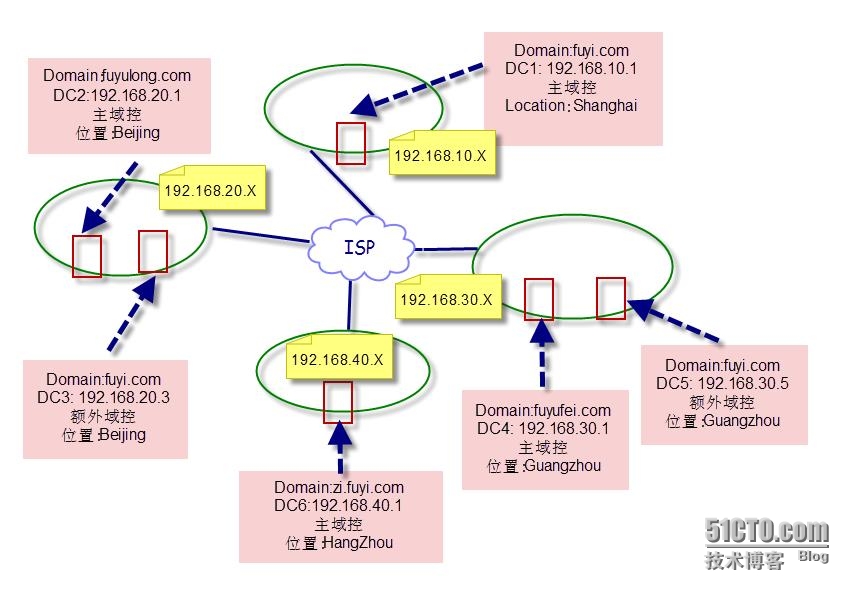
Windows 2008 R2之三十四部署活动目录轻型目录服务

本实验使用到三台虚拟机。相关配置如下图: 其中Dcsrv为DC,hbsycsrsj.com。LDDSRVA和LDDSRVB都已加入到域。 本实验将完成在Ldssrva上进行安装ADLDS实例,配置分区,并在LDDSRVA和LDDSRVB配置复制。 1、在Lddsrva上安装活动目录轻型目录服务(安装过程略) 2、在Lddsrva上配置活动目录轻型目录服务 打开管理工具中的“活动目录轻型目录服务安装向导”。 运行Adsiedit.msc.建立连接 3、同步。 在命令提示符下,改变目录到Windows\adam下,运行adschemaanalyzer打开架构分析器 打开文件菜单下的“加载目标架构” 服务器:端口,输入DC的计算机名和端口。 打开文件菜单下的加载基础架构,输入如下图 打开工具菜单下的“选项”菜单,进行如下图设置。 选择架构菜单下的“将所有非现有元素标记为已。。。。” 选择文件菜单下的创建ldif文件,保存文件为diff.ldf 执行如下图命令。 修改windows\adam文件夹下的Ms-adamsyncconf.xml文件。 运行adamsync /install localhost:389 ms-adamsyncconf.xml adamsync /sync localhost:389 “cn=parta,dc=hbsycsrsj,dc=com” /log - 结果如下图 4、安装和配置复制实例。 在计算机LDdssrvB上安装轻型目录服务。并进行如下图配置。 运行Adsiedit.msc建立如下图连接。 设置复制计划。 本文转自ycrsjxy51CTO博客,原文链接:http://blog.51cto.com/ycrsjxy/1039800,如需转载请自行联系原作者

资源下载

更多资源
Mario

Mario

马里奥是站在游戏界顶峰的超人气多面角色。马里奥靠吃蘑菇成长,特征是大鼻子、头戴帽子、身穿背带裤,还留着胡子。与他的双胞胎兄弟路易基一起,长年担任任天堂的招牌角色。

Nacos

Nacos

Nacos /nɑ:kəʊs/ 是 Dynamic Naming and Configuration Service 的首字母简称,一个易于构建 AI Agent 应用的动态服务发现、配置管理和AI智能体管理平台。Nacos 致力于帮助您发现、配置和管理微服务及AI智能体应用。Nacos 提供了一组简单易用的特性集,帮助您快速实现动态服务发现、服务配置、服务元数据、流量管理。Nacos 帮助您更敏捷和容易地构建、交付和管理微服务平台。

Rocky Linux

Rocky Linux

Rocky Linux(中文名:洛基)是由Gregory Kurtzer于2020年12月发起的企业级Linux发行版,作为CentOS稳定版停止维护后与RHEL(Red Hat Enterprise Linux)完全兼容的开源替代方案,由社区拥有并管理,支持x86_64、aarch64等架构。其通过重新编译RHEL源代码提供长期稳定性,采用模块化包装和SELinux安全架构,默认包含GNOME桌面环境及XFS文件系统,支持十年生命周期更新。

WebStorm

WebStorm

WebStorm 是jetbrains公司旗下一款JavaScript 开发工具。目前已经被广大中国JS开发者誉为“Web前端开发神器”、“最强大的HTML5编辑器”、“最智能的JavaScript IDE”等。与IntelliJ IDEA同源,继承了IntelliJ IDEA强大的JS部分的功能。

用户登录
用户注册