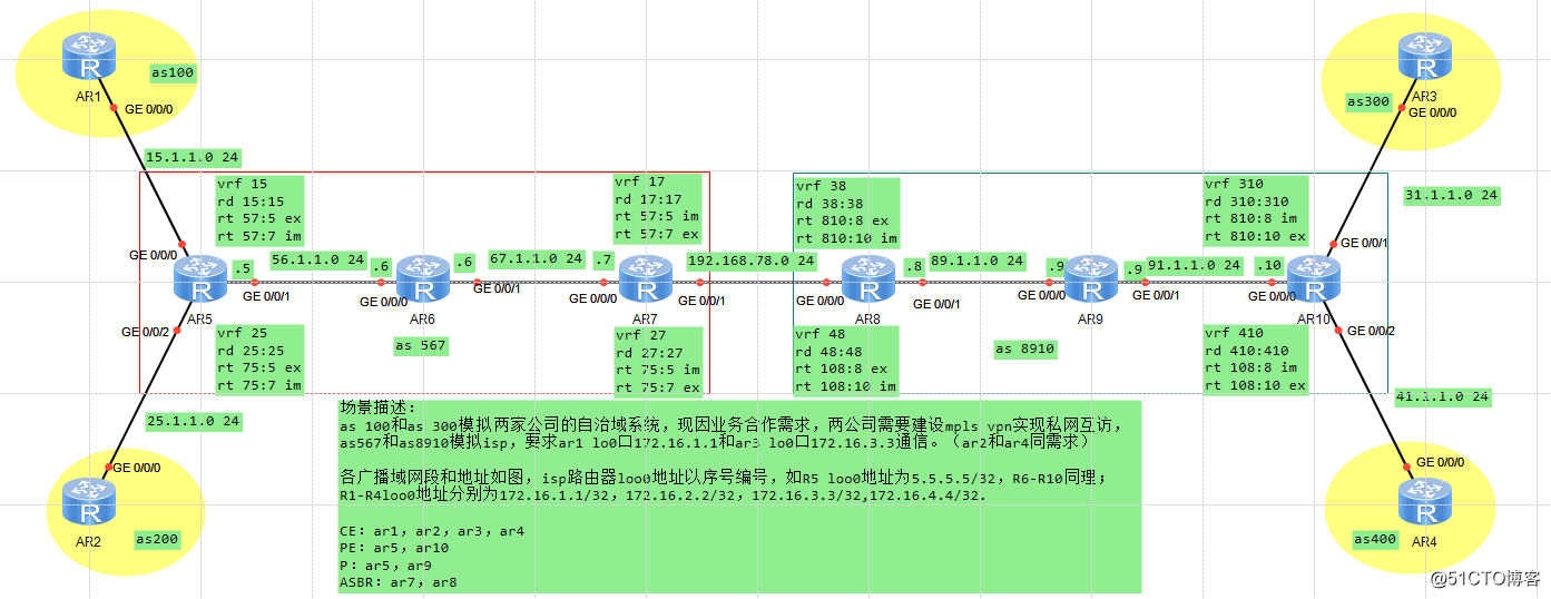
场景描述:
as 100和as 300模拟两家公司的自治域系统,现因业务合作需求,两公司需要建设mpls ***实现私网互访,as 567和as 8910模拟ISP,要求ar1 lo0口172.16.1.1和ar3 lo0口172.16.3.3通信。(ar2和ar4同需求)
各广播域网段和地址如图,isp路由器lo0地址以序号编号,如R5 lo0地址为5.5.5.5/32,R6-R10同理;R1-R4 lo0地址分别为172.16.1.1/32,172.16.2.2/32,172.16.3.3/32,172.16.4.4/32.
![MPLS OPTION A配置原理及数据通信分析]()
![MPLS OPTION A配置原理及数据通信分析]()
一、isp内部igp互通
1.1、配置所有设备ip地址,如图(具体步骤略)
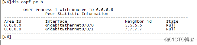
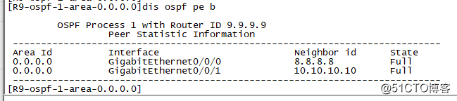
1.2、isp内建立ospf邻居,宣告环回口
R5:
ospf 1 router-id 5.5.5.5
 area 0.0.0.0
  network 5.5.5.5 0.0.0.0
  network 56.1.1.5 0.0.0.0

R6:
ospf 1 router-id 6.6.6.6
 area 0.0.0.0
  network 6.6.6.6 0.0.0.0
  network 56.1.1.6 0.0.0.0
  network 67.1.1.6 0.0.0.0

R7:
ospf 1 router-id 7.7.7.7
 area 0.0.0.0
  network 7.7.7.7 0.0.0.0
  network 67.1.1.7 0.0.0.0

R8:
ospf 1 router-id 8.8.8.8
 area 0.0.0.0
  network 8.8.8.8 0.0.0.0
  network 89.1.1.8 0.0.0.0

R9:
ospf 1 router-id 9.9.9.9
 area 0.0.0.0
  network 9.9.9.9 0.0.0.0
  network 89.1.1.9 0.0.0.0
  network 91.1.1.9 0.0.0.0

R10:
ospf 1 router-id 10.10.10.10
 area 0.0.0.0
  network 10.10.10.10 0.0.0.0
  network 91.1.1.10 0.0.0.0
查看是否已成功建立ospf邻居:
![MPLS OPTION A配置原理及数据通信分析]()
![MPLS OPTION A配置原理及数据通信分析]()
二、isp内部建立mpls隧道,使用ldp自动分发标签,解决将来的路由黑洞
R5:
mpls lsr-id 5.5.5.5
mpls
interface GigabitEthernet0/0/1
 mpls
 mpls ldp

R6:
mpls lsr-id 6.6.6.6
mpls
mpls ldp
interface GigabitEthernet0/0/1
 mpls
 mpls ldp
interface GigabitEthernet0/0/0
 mpls
 mpls ldp

R7:
mpls lsr-id 7.7.7.7
mpls
mpls ldp
interface GigabitEthernet0/0/0
 mpls
 mpls ldp

R8:
mpls lsr-id 8.8.8.8
mpls
mpls ldp
interface GigabitEthernet0/0/1
 mpls
 mpls ldp

R9:
mpls lsr-id 9.9.9.9
mpls
mpls ldp
interface GigabitEthernet0/0/1
 mpls
 mpls ldp
interface GigabitEthernet0/0/0
 mpls
 mpls ldp

R10:
mpls lsr-id 10.10.10.10
mpls
mpls ldp
interface GigabitEthernet0/0/0
 mpls
 mpls ldp
查看ldp邻居是否成功建立:
[R6]dis mpls ldp peer

 LDP Peer Information in Public network
 A '*' before a peer means the peer is being deleted.
 ------------------------------------------------------------------------------
 PeerID                 TransportAddress   DiscoverySource
 ------------------------------------------------------------------------------
 5.5.5.5:0              5.5.5.5            GigabitEthernet0/0/0
 7.7.7.7:0              7.7.7.7            GigabitEthernet0/0/1
 ------------------------------------------------------------------------------
 TOTAL: 2 Peer(s) Found.

[R6]
[R8]dis mpls ldp peer

 LDP Peer Information in Public network
 A '*' before a peer means the peer is being deleted.
 ------------------------------------------------------------------------------
 PeerID                 TransportAddress   DiscoverySource
 ------------------------------------------------------------------------------
 9.9.9.9:0              9.9.9.9            GigabitEthernet0/0/1
 ------------------------------------------------------------------------------
 TOTAL: 1 Peer(s) Found.

[R8]
三、PE设备建立v4邻居,用于将来传递路由
R5:
bgp 567
 undo default ipv4-unicast
 peer 7.7.7.7 as-number 567
 peer 7.7.7.7 connect-interface LoopBack0
 ipv4-family unicast
  undo synchronization
  undo peer 7.7.7.7 enable
 ipv4-family ***v4
  policy ***-target
  peer 7.7.7.7 enable

R7:
bgp 567
 undo default ipv4-unicast
 peer 5.5.5.5 as-number 567
 peer 5.5.5.5 connect-interface LoopBack0
 ipv4-family unicast
  undo synchronization
  undo peer 5.5.5.5 enable
 ipv4-family ***v4
  policy ***-target
  peer 5.5.5.5 enable

R8:
bgp 8910
 undo default ipv4-unicast
 peer 10.10.10.10 as-number 8910
 peer 10.10.10.10 connect-interface LoopBack0
 ipv4-family unicast
  undo synchronization
  undo peer 10.10.10.10 enable
 ipv4-family ***v4
  policy ***-target
  peer 10.10.10.10 enable

R10:
bgp 8910
 undo default ipv4-unicast
 peer 8.8.8.8 as-number 8910
 peer 8.8.8.8 connect-interface LoopBack0
 ipv4-family unicast
  undo synchronization
  undo peer 8.8.8.8 enable
 ipv4-family ***v4
  policy ***-target
  peer 8.8.8.8 enable
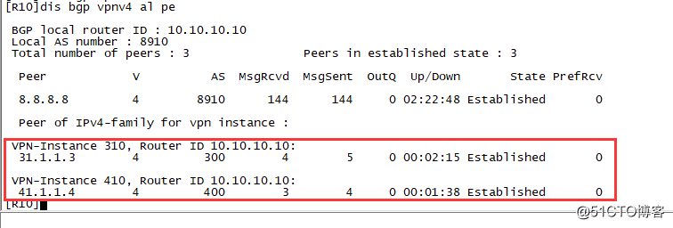
查看***v4邻居是否正常建立:
[R7]dis bgp ***v4 al pe

 BGP local router ID : 7.7.7.7
 Local AS number : 567
 Total number of peers : 1                Peers in established state : 1

  Peer            V          AS  MsgRcvd  MsgSent  OutQ  Up/Down       State PrefRcv

  5.5.5.5         4         567        7        7     0 00:05:29 Established       0
[R7]
[R10]dis bgp  ***v4 al pe

 BGP local router ID : 10.10.10.10
 Local AS number : 8910
 Total number of peers : 1                Peers in established state : 1

  Peer            V          AS  MsgRcvd  MsgSent  OutQ  Up/Down       State PrefRcv

  8.8.8.8         4        8910        2        2     0 00:00:46 Established       0
[R10]
四、建立CE与PE设备的连接
4.1、PE设备上创建vrf实例
R5:
ip ***-instance 15
 ipv4-family
  route-distinguisher 15:15
  ***-target 57:5 export-extcommunity
  ***-target 57:7 import-extcommunity
ip ***-instance 25
 ipv4-family
  route-distinguisher 25:25
  ***-target 75:5 export-extcommunity
  ***-target 75:7 import-extcommunity

R7:
ip ***-instance 17
 ipv4-family
  route-distinguisher 17:17
  ***-target 57:7 export-extcommunity
  ***-target 57:5 import-extcommunity
ip ***-instance 27
 ipv4-family
  route-distinguisher 27:27
  ***-target 75:7 export-extcommunity
  ***-target 75:5 import-extcommunity

R8:
ip ***-instance 38
 ipv4-family
  route-distinguisher 38:38
  ***-target 810:8 export-extcommunity
  ***-target 810:10 import-extcommunity
ip ***-instance 48
 ipv4-family
  route-distinguisher 48:48
  ***-target 108:8 export-extcommunity
  ***-target 108:10 import-extcommunity

R10:
ip ***-instance 310
 ipv4-family
  route-distinguisher 310:310
  ***-target 810:10 export-extcommunity
  ***-target 810:8 import-extcommunity
ip ***-instance 410
 ipv4-family
  route-distinguisher 410:410
  ***-target 108:10 export-extcommunity
  ***-target 108:8 import-extcommunity

4.2、PE设备接口绑定vrf实例
R5:
interface GigabitEthernet0/0/0
 ip binding ***-instance 15
 ip address 15.1.1.5 255.255.255.0
interface GigabitEthernet0/0/2
 ip binding ***-instance 25
 ip address 25.1.1.5 255.255.255.0

R10:
interface GigabitEthernet0/0/1
 ip binding ***-instance 310
 ip address 31.1.1.10 255.255.255.0
interface GigabitEthernet0/0/2
 ip binding ***-instance 410
 ip address 41.1.1.10 255.255.255.0
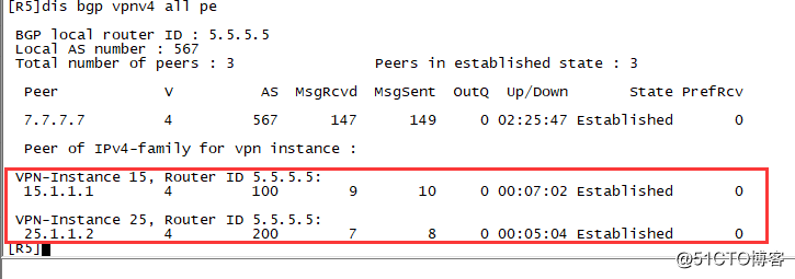
4.3、PE与CE建立bgp ipv4邻居关系
R5:
bgp 567
 ipv4-family ***-instance 15
  peer 15.1.1.1 as-number 100
 ipv4-family ***-instance 25
  peer 25.1.1.2 as-number 200

R1:
bgp 100
 peer 15.1.1.5 as-number 567
 ipv4-family unicast
  undo synchronization
  peer 15.1.1.5 enable

R2:
bgp 200
 peer 25.1.1.5 as-number 567
 ipv4-family unicast
  undo synchronization
  peer 25.1.1.5 enable

R10:
bgp 8910
 ipv4-family ***-instance 310
  peer 31.1.1.3 as-number 300
 ipv4-family ***-instance 410
  peer 41.1.1.4 as-number 400

R3:
bgp 300
 peer 31.1.1.10 as-number 8910
 ipv4-family unicast
  undo synchronization
  peer 31.1.1.10 enable

R4:
bgp 400
 peer 41.1.1.10 as-number 8910
 ipv4-family unicast
  undo synchronization
  peer 41.1.1.10 enable
查看是否成功建立ipv4邻居关系:
![MPLS OPTION A配置原理及数据通信分析]()
![MPLS OPTION A配置原理及数据通信分析]()
五、使用子接口,建立asbr的bgp连接
R7:
interface GigabitEthernet0/0/1.13
 dot1q termination vid 13
 ip binding ***-instance 17
 ip address 192.168.78.7 255.255.255.0
 arp broadcast enable
interface GigabitEthernet0/0/1.24
 dot1q termination vid 24
 ip binding ***-instance 27
 ip address 192.168.78.7 255.255.255.0
 arp broadcast enable
bgp 567
 ipv4-family ***-instance 17
  peer 192.168.78.8 as-number 8910
 ipv4-family ***-instance 27
  peer 192.168.78.8 as-number 8910

R8:
interface GigabitEthernet0/0/0.13
 dot1q termination vid 13
 ip binding ***-instance 38
 ip address 192.168.78.8 255.255.255.0
 arp broadcast enable
interface GigabitEthernet0/0/0.24
 dot1q termination vid 24
 ip binding ***-instance 48
 ip address 192.168.78.8 255.255.255.0
 arp broadcast enable
bgp 8910
 ipv4-family ***-instance 38
  peer 192.168.78.7 as-number 567
 ipv4-family ***-instance 48
  peer 192.168.78.7 as-number 567
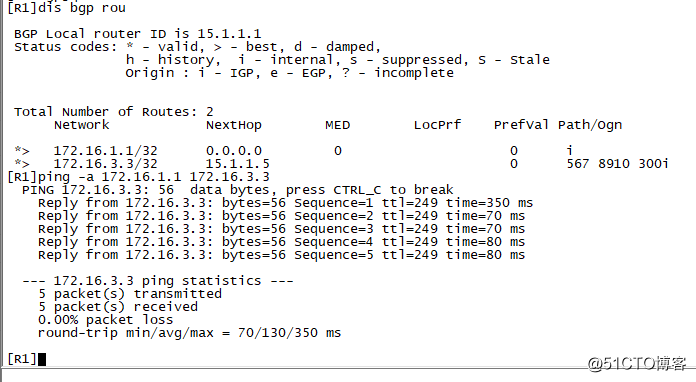
六、在CE设备上用bgp宣告路由
R1:
bgp 100
network 172.16.1.1 255.255.255.255
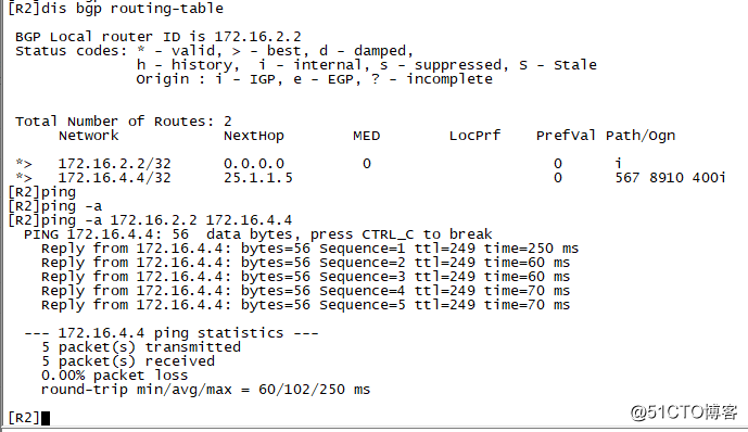
R2:
bgp 200
network 172.16.2.2 255.255.255.255
R3:
bgp 300
network 172.16.3.3 255.255.255.255
R4:
bgp 400
network 172.16.4.4 255.255.255.255
七、测试
![MPLS OPTION A配置原理及数据通信分析]()
![MPLS OPTION A配置原理及数据通信分析]()
八、注意点
8.1、PE设备连接CE时,除了用bgp外,也可以用ospf、isis等igp协议,但这样做的话就必须在PE、CE设备上都执行双向引入;
8.2、mpls lsr-id 路由必须可达,且需要是32位路由,因为ldp默认只为32位路由分配标签;
九、数据通信分析
9.1、路由传递路径分析
R1使用bgp传递lo0路由172.16.1.1/32给R5,172.16.1.1/32通过R5的g/0/0/0口进入vrf 15,路由被打上RD变成96位的v4路由,因为R5和R7位mp-bgp邻居且出入RT值匹配,所以R7可以接收R5传来的172.16.1.1/32的路由并进入R7的vrf 17(此路由携带内网标签);R7的g0/0/1.13绑定vrf 17,右半部分的所有设备被R7当做vrf 17的CE,所以R7会把接收到的路由172.16.1.1/32进入vrf 17后的ipv4路由传递给R8;R8也把左半边设备当做CE,所以172.16.1.1/32会进入vrf 38并打上RD变成路由,再根据RT出入值发送给R10(此路由携带内网标签);R10收到1.1.1.1/32后加入vrf 310并把ipv4路由发送给bgp邻居R3,R3至此收到了172.16.1.1/32.
9.2、数据流量分析
R3查看全局路由表,发送目的地址为172.16.1.1的数据包给31.1.1.10;R10查看-instance 310,在ip层下压入内网标签(用于告诉R8该查哪张路由表),再压入外网标签(用于解决as8910的路由黑洞);数据包到达R8后查找-instance 38路由表进入R7;R7查找-instance 17路由表并压入内网、外网标签,到达R5;R5查找-instance 15路由表转发给R1.
十、优缺点
优点:原理简单,便于理解,只是将ASBR所连接的另一个AS当做CE,然后通过子接口建立BGP邻居
缺点:配置过程繁琐,在需要建立多个通道的时候,ASBR上创建的子接口会很多;且ASBR需要维护路由,有违背MPLS ***路由传递按照CE1-PE1-PE2-CE2路线的理念。